Dental 3D Printing Supports: Where and How to Place Them
Two parts printed from the same design, with the same resin and the same printer, can fit differently simply because their supports were placed differently. Supports hold the part during printing, but when they sit in the wrong place, are spaced too far apart or are too thick, they can reduce accuracy, and they always leave a mark where they are removed. In this article we have compiled what DOI-indexed studies say about support placement, spacing (density), tip and shaft diameter, and support removal in dental parts. None of the numbers below were obtained with 3mash resins or printers; each belongs to the printer, resin and part used in that particular study.
What are support structures in dental 3D printing?
Support structures are temporary columns that attach a resin 3D-printed part to the build platform, carry overhanging areas and are removed after printing. Each cured layer has to separate from the vat film, which puts a peel force on the part; supports help the part keep its shape against that force. Slicing software describes supports with four basic settings:
Placement: which surface of the part the support touches.
Spacing (density): the distance between neighbouring contact points. Smaller spacing means denser supports.
Tip (contact) diameter: the diameter of the very top of the support, where it touches the part.
Shaft (middle) diameter: the diameter of the middle section, which sets how strong the support is.
Supports change together with build orientation: when the angle changes, the number and position of supports change too. We cover angle selection in our build orientation article.
Where should supports be placed on a dental part?
Supports should be kept away from the fitting (intaglio) surface, the finish line and functional contact surfaces, and placed on the outer (cameo) surface wherever possible. Here is what the studies say:
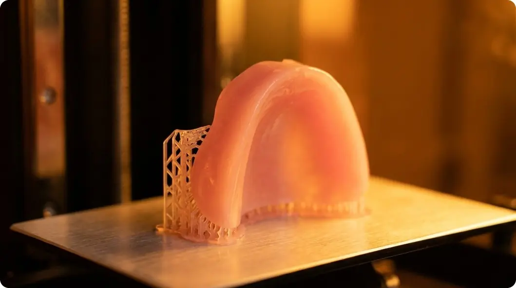
Figure 1: Support placement on a denture base
Denture bases, AlGhamdi and Gad (2024), systematic review: Accuracy was higher in denture bases whose supports and additional struts were placed on the outer (cameo) surface. The review concludes that support position has more effect than support density. All but one of the included studies kept supports away from the tooth sockets. Removing supports can also cause distortion where they were attached.
Crowns, splints and dentures, Sabanik et al. (2026), review: For crowns, the review recommends an orientation with the intaglio facing away from the build plate and light, thin supports on external surfaces. For denture bases, supports are most critical on thin areas and overhangs, while density can be reduced on the palatal and border areas. For denture teeth, the review's table suggests fine supports on the occlusal surface, which means supports must then be removed and finished on that surface.
DLP parameters, Zhang et al. (2026), review: Build orientation should be adjusted first so that supports do not land on critical surfaces. According to the review, horizontal spans over 5 mm or angles over 45° usually need support. Too many supports lower surface quality, increase material use and complicate post-processing.
Do not print directly on the plate: The first layers are deliberately overexposed to help the part stick to the platform. Sabanik et al. (2026) note that this can distort features at the platform interface (so-called "elephant footing"), so critical surfaces should not be printed directly on the build plate. For denture bases, AlGhamdi and Gad (2024) likewise advise against printing the part directly on the platform without supports.
How do support spacing and density affect accuracy?
When spacing is too wide, unsupported spans grow and the part flexes more easily during printing. The effect of density, however, is not the same for every part.
Dental models, Alpöz et al. (2026): Three-unit bridge preparation models (8 per group) were printed on an AccuFab-L4D MSLA (LCD) printer with M-PRINT Model Sand resin at 50 µm layers, using 3, 5 and 7 mm support spacing. All other support settings were kept constant. Global deviation (RMS) was 244.5 µm at 3 mm, 295.0 µm at 5 mm and 359.1 µm at 7 mm; the difference between 3 mm and 7 mm was significant. On the prepared tooth surfaces (intaglio region), deviation was 159.4 µm at 3 mm and 171.4 µm at 7 mm. At the finish line there was no linear trend: the lowest deviation was at 5 mm (52.0 µm) and the highest at 3 mm (63.9 µm). Adjacent tooth surfaces were not significantly affected. The authors say 3 mm gave the most consistent results overall, but stress that this is not a universal recommendation for every workflow.
Removable partial denture frameworks, Hussein and Hussein (2022, J Adv Prosthodont): Frameworks printed on an Asiga Max UV DLP printer with DentaCast castable resin were compared at 50% and 75% support density. For maxillary frameworks, mean deviation (RMSE) was 0.088 mm at 50% and 0.068 mm at 75%; the difference was not statistically significant. No significant difference was found for mandibular frameworks either. In this study, build orientation was what really changed accuracy.
Crowns, Sabanik et al. (2026): According to the review, studies on the internal fit of printed crowns found that reducing support density did not harm fit.
Starting value, Zhang et al. (2026): Because systematic studies on support density are limited, manufacturer guidelines commonly recommend 5 mm contact spacing for routine work. Heavy or deformation-prone areas may need denser support.
These results do not contradict each other; they come from different parts. Spacing can matter on a thin model with wide spans, while density may make less difference on a crown or framework whose supports are already concentrated on the outer surface.
What support tip and shaft diameter should you use?
A thin tip leaves a smaller mark and is easier to remove, but the shaft has to carry the part as it gets heavier.
Zhang et al. (2026), DLP review: A tip diameter of 0.4 mm is typically recommended for most dental resins as a balance between strength and ease of removal. Shaft (middle) diameters generally range from 0.6 to 1.2 mm and can be increased to 1.8–2.0 mm for heavy or tall regions to prevent fracture.
Hussein and Hussein (2022, Materials): Sixty removable partial denture frameworks were printed on an Asiga Max UV DLP printer with DentaCast resin at three build angles (110°, 135°, 150°) and two support diameters (thin 1.2 mm, thick 1.5 mm). The most accurate group was 150° with thin supports (RMS 0.061 mm); the least accurate was 110° with thick supports (RMS 0.098 mm). Colour maps of the thick-support groups generally showed more intense deviations. At the same angle, support diameter did not change print time, but thick supports used more resin: consumption was highest at 150° with thick supports (5.26 mL) and lowest at 110° with thin supports (2.39 mL).
Sabanik et al. (2026): For crown internal fit, thinner supports are preferable.
Note: these values come from specific printers and resins. The support profile recommended for your own resin and printer should always be your starting point.
Should supports be removed before or after post-curing?
There is no single correct sequence; the resin's instructions for use decide. Hassanpour et al. (2024) also point out that the order of post-processing steps is not fixed and can be adjusted for each resin. These are the sequences used in the studies:
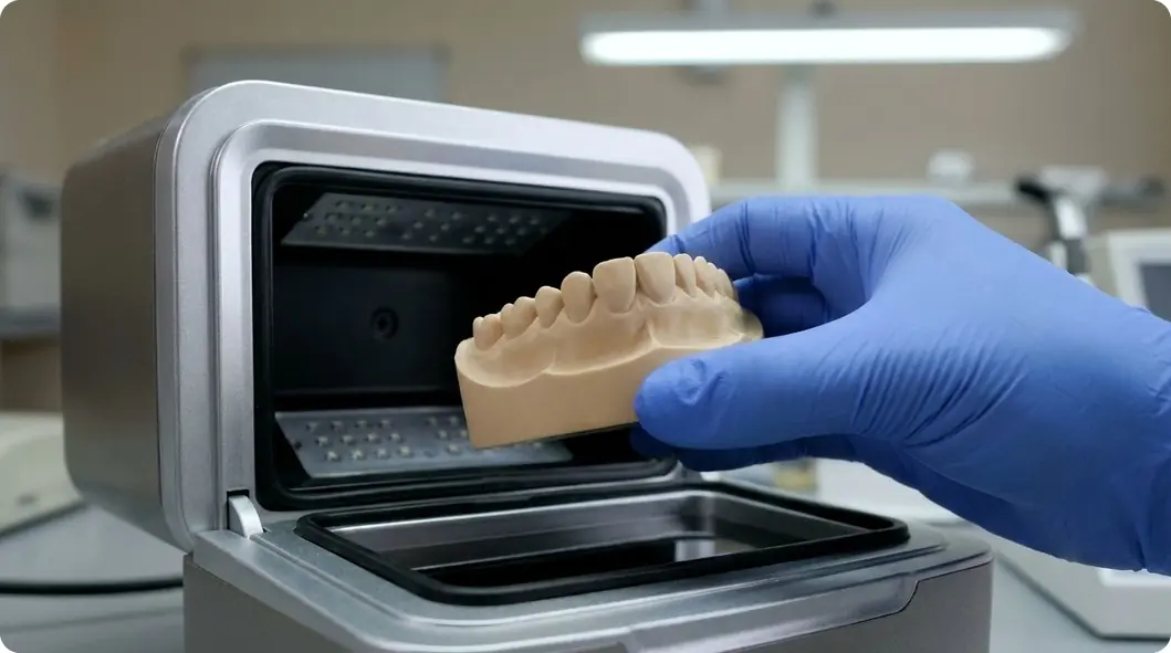
Figure 2: Final post-curing
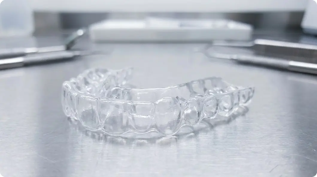
Directly printed clear aligners, Avolese et al. (2026): Upper and lower aligners designed for 10 people were printed twice each on a SprintRay Pro95 DLP printer with Tera Harz TC-85 DAC resin. In one copy the supports were removed by hand before final curing; the other was cured with the supports still attached. Mean deviation (RMS) was 0.7656 mm when supports were removed first and 0.1827 mm when cured with supports (p < 0.0001). The mean difference in inter-second-molar distance from the design was 3.59 mm and 0.55 mm, respectively. Important: the authors note that this resin's manufacturer specifies removing the supports before final curing. So this result is not a reason to change the instructions on your own; it shows how sensitive thin, not-yet-cured parts are to handling.
Dental models, Alpöz et al. (2026): Models were washed and given an initial post-cure, then the supports were removed and a second post-cure was applied to the exposed surfaces.
Removable partial denture frameworks, Hussein and Hussein (2022): In both studies, supports were removed after the frameworks were washed and cured; the authors state that curing was needed for the frameworks to gain enough strength without distortion.
How do you remove supports without damaging the surface?
Support removal means separating each support from the part with a tool, in a controlled way, rather than bending the part or tearing the supports off.
Figure 3: 3D-printed clear aligner
Tools: Hassanpour et al. (2024) report that a sharp, hardened knife, a spatula, a diamond disc or an ultrasonic tip is used to avoid breakage and uneven surfaces when detaching parts and cleaning off supports. Zhang et al. (2026) describe manual removal with scissors or fine instruments as the typical method and stress careful handling to protect the surface, even though it takes time.
Marks and distortion at attachment points: Sabanik et al. (2026) note that more supports mean more material and longer post-processing, and can leave surface defects or inaccuracies after removal. AlGhamdi and Gad (2024) also report that removing supports and struts can cause distortion in the attachment area.
Step by step: how to place and remove supports
Start with the manufacturer's guidance. The orientation, support profile and removal/curing sequence recommended for your resin and printer are your starting point. The steps below do not replace them.
Mark the critical surfaces. The fitting (intaglio) surface, finish line, tooth sockets, partial denture rests and clasps, and contact points should stay free of supports.
Choose the orientation accordingly. Orient the part so that supports land on the outer (cameo) surface. Do not print a critical surface directly on the platform.
Put support where it is needed. Thin areas, overhangs and wide spans come first. Density can often be reduced in areas such as the palate, but on models, spacing that is too wide can increase deviation.
Start with a thin tip. For heavy or tall parts, increase the shaft diameter rather than making the tip unnecessarily thick.
Remove supports with a tool. Cut each support close to the part surface with a sharp tool; do not bend the part. Take extra care with thin, flexible parts.
Follow the removal and curing order in the instructions. Where the instructions allow it and the part is thin, avoid forcing an uncured part by hand.
Finish the marks and check the fit. Smooth the attachment points and check the part on the model or by scanning. Test any new support setting on a few parts first.
Why do the study results differ?
The studies used different printers (MSLA/LCD and DLP), different resins (model, castable and aligner resins) and different parts. Sample sizes were small; the spacing study had 8 models per group. These differences come from study conditions rather than from the technology itself, and the findings do not show that DLP or LCD printers are superior to one another. Washing is another step that affects accuracy; see our washing guide.
Conclusion
Support structures affect accuracy, surface quality and post-processing time all at once. In the studies reviewed, keeping supports on the outer surface, leaving critical surfaces free, using thin tips and not spacing supports too widely on models stood out. When to remove supports depends on the resin. For 3mash dental 3D printing resins and 3D printers, follow the product's own guidance for support settings and the removal/curing sequence, and contact the 3mash technical support team with any questions.
Frequently asked questions
Where should supports not be placed in dental 3D printing?
Supports should not be placed on the fitting (intaglio) surface, the finish line, tooth sockets or functional contact points. According to the reviews, placing supports on the outer (cameo) surface improves denture base accuracy, and thin supports on external surfaces are recommended for crowns.
What support spacing should I use?
There is no single correct value. Zhang et al. (2026) note that manufacturer guidelines commonly recommend 5 mm for routine work. Alpöz et al. (2026) found that 7 mm spacing gave significantly more global deviation than 3 mm on MSLA-printed models. Use the profile for your own resin and printer.
Are denser supports always more accurate?
No. Hussein and Hussein (2022) found no significant accuracy difference between 50% and 75% density in DLP-printed partial denture frameworks, and reducing density did not harm the internal fit of crowns. Excess supports increase resin use, post-processing time and surface marks.
What support tip diameter should I use?
According to the review by Zhang et al. (2026), a 0.4 mm tip is typically recommended for most dental resins, with shafts of 0.6–1.2 mm and 1.8–2.0 mm for heavy regions. These values are a starting point and do not replace the manufacturer's profile.
Should I remove supports before post-curing?
Follow your resin's instructions. Avolese et al. (2026) found that aligners cured with supports attached were more accurate for one aligner resin, but that resin's manufacturer specifies removing supports before curing. In the model and framework studies, supports were removed after curing.
References
Alpöz B, Akan B, Akan E. Effect of Support Spacing on the Region-Specific Dimensional Accuracy of 3D-Printed Dental Models. Materials. 2026;19(16):3463. https://doi.org/10.3390/ma19163463
Hussein MO, Hussein LA. Optimization of Digital Light Processing Three-Dimensional Printing of the Removable Partial Denture Frameworks; The Role of Build Angle and Support Structure Diameter. Materials. 2022;15(6):2316. https://doi.org/10.3390/ma15062316
Hussein MO, Hussein LA. Trueness of 3D printed partial denture frameworks: build orientations and support structure density parameters. The Journal of Advanced Prosthodontics. 2022;14(3):150–161. https://doi.org/10.4047/jap.2022.14.3.150
Avolese S, Sanna F, Parrini S, Chiarello G, Lava D, Sedran A, Deregibus A, Scotti N. Evaluation of the Dimensional Accuracy of 3D-Printed Aligners: An In Vitro Study Using Reverse Engineering Analysis. Journal of Functional Biomaterials. 2026;17(1):22. https://doi.org/10.3390/jfb17010022
Zhang Y, Wang J, Wang P, Tang S, Xue C. Printing parameters for digital light processing three-dimensional printing in dentistry: A practice-oriented narrative review. International Journal of Bioprinting. 2026;12(2):026110089. https://doi.org/10.36922/IJB026110089
Sabanik P, Liu T, Tabatabaeian M, Rocha MG, Surathu N, Lawson NC. A Review of Current Systems, Materials, and Protocols for 3D-Printed Splints, Crowns, and Dentures. Journal of Esthetic and Restorative Dentistry. 2026;38(3):635–651. https://doi.org/10.1111/jerd.70125
Hassanpour M, Narongdej P, Alterman N, Moghtadernejad S, Barjasteh E. Effects of Post-Processing Parameters on 3D-Printed Dental Appliances: A Review. Polymers. 2024;16(19):2795. https://doi.org/10.3390/polym16192795
AlGhamdi MA, Gad MM. Impact of Printing Orientation on the Accuracy of Additively Fabricated Denture Base Materials: A Systematic Review. Dentistry Journal. 2024;12(7):230. https://doi.org/10.3390/dj12070230